Solenoid Door Lock Arduino

Relay Module Solenoid Door Lock How To Control Them With An Arduino Door Locks Arduino Programming Tutorial

Arduino Solenoid Door Lock Using Rfid In 2020 Arduino Rfid Arduino Arduino Circuit

Solenoid Door Lock Arduino In 2020 Arduino Arduino Robot Arduino Projects

Arduino Solenoid Door Lock Using Rfid In 2020 Arduino Arduino Projects Door Locks

Controlling A Lock With An Arduino And Bluetooth Le Make Arduino Arduino Projects Bluetooth

Arduino Solenoid Door Lock Using Rfid In 2020 Rfid Arduino Arduino Arduino Projects

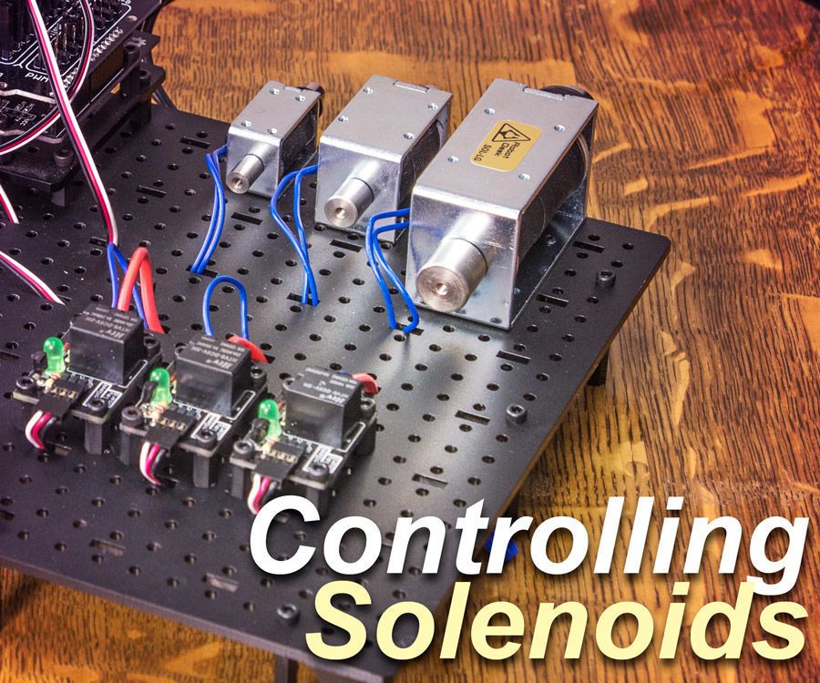
In this instructable we will be building a simple circuit that will allow us to control a solenoid using the popular physical computing platform arduino.
Solenoid door lock arduino.

Controlling A Lock With An Arduino And Bluetooth Le Make Arduino Arduino Projects Bluetooth Gadgets

Solenoid Door Lock Contol Rfid Arduino Arduino Arduino Contol Door Lock Rfid Solenoid In 2020 Rfid Arduino Arduino Projects Diy Arduino

Solenoid Door Lock In 2020 Door Locks Door Lock System Arduino

Open Electric Door Lock Using Rfid Reader Security Access With Arduino Youtube Rfid Arduino Arduino Projects Diy Arduino

Arduino Door Lock With Password Arduino Arduino Projects Door Locks

Arduino Solenoid Door Lock Using Rfid Youtube In 2020 Arduino Arduino Projects Door Locks

Arduino Controlled Lock Box With Solenoid And Rfid Lockbox Electronics Projects Arduino

Arduino Rfid Door Lock In Action Rfid Arduino Arduino Rfid

Learn How To Make An Rfid Door Lock Powered By An Arduino And Solenoid Engine Rfid Arduino Arduino Arduino Sensors

F I V O D On Instagram How To Make Fingerprint Door Lock At Home You Need Adafruit Fingerprint Sensor Fingerprint Door Lock Fingerprint Lock Door Locks

Automatic Garden Watering System By Arduino Lcd Buttons Eeprom Solenoid Valve Motor And Underground Sprinkler Garden Watering System Underground Sprinkler Arduino

Arduino Rfid Solenoid Lock Youtube In 2020 Rfid Arduino Rfid Arduino

Arduino Rfid Door Lock Access Control Project Arduino Door Locks Arduino Projects

Unlock A Door With An Arduino And Your Smartphone Bluetooth Lock Smartphone Arduino

Pin On Instructibles

Arduino Keypad Password Arduino Arduino Lcd Arduino Projects

Remote Controlled Door Lock Using A Fingerprint Sensor Adafruit Io Remote Control Door Lock Door Locks Lock Style

Arduino Door Lock Using 4 4 Keypad And Servo Motor Program And Video Http Www Letsarduino Com Electronics Projects Electronics Projects Diy Diy Electronics

Arduino Door Lock With Password Door Locks Arduino Electric Lock
Control A Solenoid With Arduino Arduino Arduino Projects Radio Control Diy

Multi Task Arduino Uno Projets Arduino Arduino Electronique

Open Source Bluetooth Door Lock Make Diy Electronics Arduino Projects Smart Door Locks

Electric Lock Assembly Solenoid Cabinet Drawer Door Lock 12v Dc 1 1a Electronicslovers Official Store Electric Lock Electricity Drawers

Pin On Access Control Equipment Facility Maintenance And Safety

Dc 12 V 24 V Open Type De Cadre Magnetique Pour Serrure De Porte Electrique Lcc77 Pintu Listrik Jenis

Fingerprint Door Unlock System Arduino Keeping You Safe Arduino Electronics Projects Finger Print Sensor

Easy Bluetooth Enabled Door Lock With Arduino Android Door Handles Door Locks Security Locker

Pin On Future Tech

Http Bildr Org Blog Wp Content Uploads 2012 03 Rfp30n06le Arduino Solenoid Png Arduino Projects Arduino Motor Arduino

Automated Dust Collection Blast Gate I Saw On Youtube Uses Standard 12v Automotive Solenoid Could Be Paired With Ar In 2020 Dust Collection Homemade Tools Ute Canopy

Open Source Bluetooth Door Lock Make Diy Electronics Arduino Projects Smart Door Locks

Arduino Rfid Door Lock Arduino Engenharia

How To Use Bh1750 Ambient Light Sensor With Arduino Light Sensor Arduino Light Sensor Circuit
Arduino Rfid Door Lock Hardware Project Setup Arduino Rfid Arduino Rfid

High Quality 10 Pcs Dc12v 350ma Ultra Compact Locks Free Shipping Cabinet Door Electric Lock Assembly Solenoid Electric Lock Cabinet Doors Doors

Electric Lock Catch Release Assembly Solenoid For Door Gate Drawer 12v 0 34a Electric Lock Catch Release Asse Electronic Lock Access Control Electric Lock

Wifi Internet Controlled Relays Using Esp8266 Quick 30 Minutes Iot Project Iot Projects Arduino Wifi Internet

12v 24v Generic Cabinet Door Electric Lock Tongue Right Assembly Solenoid Electric Lock Electronic Lock Door Lock Security

Arduino Rfid Door Lock Access Control Project Access Control Control Arduino

How To Use A High Current Solenoid With Arduino Arduino Arduino Being Used Current

New Safurance Dc 12v 0 5a Mini Electric Bolt Lock Push Pull Cylindrical Cabinet Lock 5mm Stroke Access Control Home Secur Electric Bolt Cabinet Locks Bolt Lock

Circuit Diagram For Arduino Based Text To Speech Tts Converter Arduino Circuit Diagram Speech

Arduino Robot Arduino En 2020

How To Make Remote Control Door Lock At Home Diy Electric Project Remote Control Door Lock Diy Lock Remote Door Lock
Source : pinterest.com
